Work Project
STARS: a refueling and relay platform at Earth–Moon L1
A ten-person mission proposal for a propellant depot and lunar communications relay in a halo orbit around the Earth–Moon L1 point.
Ten aerospace students sized a station in a halo orbit around Earth–Moon L1 that refuels lunar-bound spacecraft and relays data from the lunar south pole and far side, all closed around one Falcon Heavy launch.
Why it matters for GNC. Choosing the halo orbit, sizing station-keeping thrust, picking attitude sensors and actuators, and placing relay satellites in frozen lunar orbits are the mission-level decisions that guidance and navigation work serves.
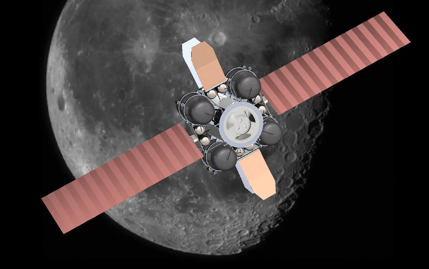
STARS in its operating configuration. Eight composite tanks hold the green monopropellant; the arrays track the Sun on a single gimbal axis.
Team render, STARS report.The problem
The Earth–Moon L1 point is an equilibrium point of the rotating Earth–Moon system, roughly 58,000 km from the Moon on the Earth side. Orbits around it are unstable, so anything parked there must keep station. In exchange, a halo orbit around L1 keeps constant line of sight to both Earth and the lunar south pole, and most trajectories into lunar space pass within reach.
The project answered NASA’s RASC-AL theme for a multi-use platform at L1. STARS answers it with two services: refueling for medium-sized spacecraft, and a communications relay. The relay has two layers: a high-rate link from the lunar south pole to Earth through the platform, and eight CubeSats (COMeT) that give lower-rate coverage of most of the lunar surface, including the far side.
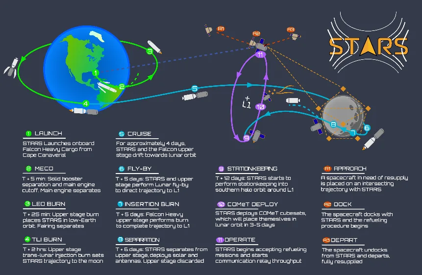
Concept of operations, from launch through a lunar flyby to a south-facing halo orbit, CubeSat deployment and refueling.
Team figure, STARS report Fig. 1.My part
STARS was a ten-person effort, and the report is a joint document. The figures and numbers on this page are the team’s.
Architecture and budgets
Everything had to fit a single expendable Falcon Heavy, which can put 15,000 kg on a trans-lunar trajectory. The team first sized STARS for SLS, then cut it down because the cheaper launch outweighed the lost refueling capacity.
| Item | Value in the report |
|---|---|
| Halo orbit | 3,500 km radius, 12-day period, worst-case solar occlusion 0.793% per orbit |
| Mass | 11,351 kg with margin against 15,000 kg to trans-lunar injection, leaving about 3,650 kg for rideshare |
| Propellant | LMP-103S green monopropellant: about 4,700 kg for station-keeping and attitude, 2,600 kg to transfer |
| Refueling | Three 800 kg transfers, or more smaller ones, through ESA’s automatic transfer docking port |
| Attitude | Two Ball CT-2020 star trackers, two sun sensors, a Honeywell miniature IMU, four TELDIX RSI 68-75/60 wheels |
| Power | 12 m² of GaAs arrays, about 2.4 kW; 14.5 kWh of batteries |
| Links | X-band. Platform to Earth: 150 Mbps up, 400 Mbps down on phased arrays. COMeT: 50 Mbps each way |
| Cost | 190.5 M launch, $2.51 B in 2030 dollars (USCM8 model) |
The halo orbit’s size traded station-keeping cost against how easily arriving spacecraft could reach the platform. Its short eclipses meant smaller batteries, and the mass saved went into refueling propellant.
Station-keeping thrust
The report sizes the thrusters from burn assumptions rather than a propagated trajectory: 35-second burns, about 0.56 burns a day and a 20% safety factor give roughly 183 N per burn, plus 5 N to desaturate the wheels. With an average thruster of 12 N:
That became four 22 N, eight 10 N and four 5 N thrusters, placed so each one acts on more than one axis.
The station-keeping budget comes from assumed burn length and frequency. Nobody propagated the halo orbit with a control law, so the 183 N figure is a sizing estimate, not a simulated result.
Attitude determination and control
Star trackers are the primary reference, mounted so at least one always looks away from the Sun, Earth and Moon. Sun sensors keep the arrays roughly pointed if the primary fails. The IMU gives high-rate state estimates between star-tracker updates. The wheels run as momentum wheels: their stored momentum stiffens the platform against docking loads, and the thrusters dump excess momentum.
The COMeT relay constellation
Eight 6U CubeSats fly frozen lunar orbits from Folta and Quinn (2006), so they need little station-keeping over ten years: two planes of four, inclination 52°, eccentricity 0.6119, argument of periapsis 90° or 270°, period 13 hours.
Checked for this page: with the Moon’s μ = 4,902.8 km³/s², a 13-hour period gives a = 6,479 km. At e = 0.6119, periapsis sits about 780 km above the surface and apoapsis about 8,710 km, consistent with the report’s 800 km.
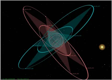
COMeT orbit planes around the Moon.
Team figure.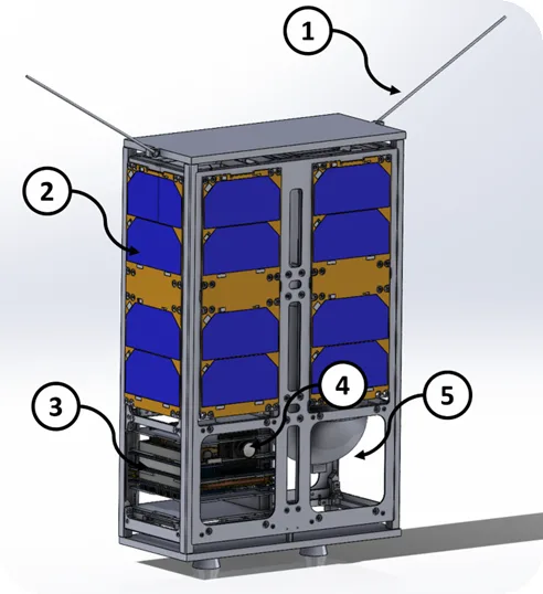
A COMeT CubeSat on an EnduroSat 6U bus: dipole antennas, fixed panels, avionics stack, star tracker and a monopropellant tank.
Team figure.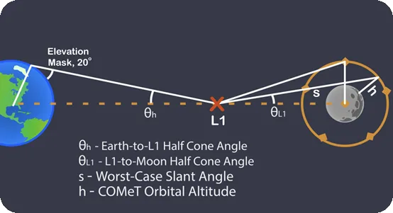
Link geometry used for the link budgets: Earth-to-L1 and L1-to-Moon half-cone angles, the worst-case slant angle and a 20° elevation mask.
Team figure.Results
The mass budget closes with about a quarter of the launch capacity to spare, and every listed component is at TRL 7 or higher except the green-propellant thrusters, at TRL 6, which the team named as the schedule driver. The team flagged three operational risks and designed for each: propellant slosh (more, smaller tanks with baffles), the new thrusters (redundant thrusters and plumbing) and single-event upsets (radiation-hardened, redundant electronics).
With its 30% margin the power budget comes to 2.51 kW, above the arrays’ roughly 2.4 kW; the report does not reconcile the two. The cost is a parametric estimate.
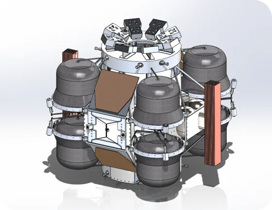
The platform with arrays stowed for launch.
Team render.Lessons
Coordinating ten schedules was the hardest part early on. Knowledge gaps and miscommunication shrank once the team met regularly in person to work on the core design. The technical follow-up I would do now is the part the proposal assumed: compute the halo orbit itself in the circular restricted three-body problem and run a Monte Carlo of station-keeping cost.
Documents
- STARS final reportTeam document, December 2022. 15 pages including link budgets and component TRLs.