Work Research
A loading rig for six-axis load-cell error characterization
A compact fixture that applies known axial, transverse and moment loads to a strain-gauge load cell at the same time, so its error terms can be measured.
Wind-tunnel balances drift through creep, hysteresis, temperature and orientation, and a measurement is only as good as its calibration. I designed and built a rig that loads an Interface 6A40 six-axis load cell through two preloaded springs, in steps of known force, so those errors could be measured.
Why it matters for GNC. An estimator is only as good as its sensor model. This rig exists to measure one: the error terms of a six-axis force sensor.
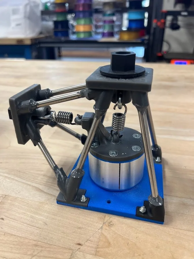
The finished rig with the aluminum stand-in for the load cell installed.
The problem
Load cells in experimental aerodynamics turn the forces and moments on a wind-tunnel model into strain-gauge signals. Like any instrument they drift: hysteresis between loading and unloading, creep under a constant load, thermal drift as tunnel flow changes the gauges’ temperature, and possibly a dependence on orientation. To quantify those errors you need to apply loads you already know, precisely, and hold them.
The sensor was an Interface 6A40: a cylinder 2.4 in across and 1.6 in tall that measures force and moment on all three axes. Its limits set the design envelope: 50 N transverse and 200 N axial force, 5 N·m about each axis.
Design
First concept, rejected
The first concept hung the springs from an outer MDF box around a printed inner stand. Cutting and joining MDF would stack tolerance errors into the applied load, and a single M6 bolt to the orientation stand would have been an unstable mount.
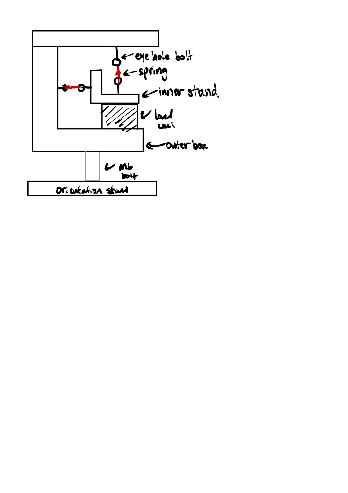
The first concept: an outer box, an inner stand and one bolt to the stand.
Redesign: a truss instead of a box
The redesign replaced the box with a truss of 6 mm stainless tubes and resin-printed joints on a 4 × 4 in base: more compact, stiffer and with far fewer joints to get wrong. Several final dimensions were still unknown, so I modeled the whole assembly parametrically in SolidWorks against a set of reference planes. Changing one dimension rebuilt the rest. The angled tube connectors came from surface operations, the one part of the model that needed manual repair after large changes.
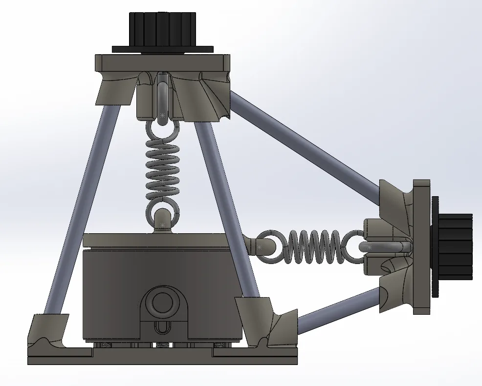
Side view. The top spring loads the cell axially; the side spring pulls transversely through a hoop one inch above the cell’s moment plane.
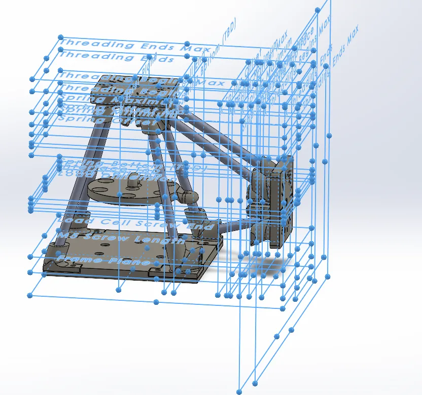
Reference planes that drive the parametric model.
Knowing the applied load
Each spring hangs from an eyebolt in a 10-24 thread. Turning the knob draws the eyebolt up, and notches every 15° on the knob and its mount count the turns. One notch stretches the spring by a known amount:
where k is the catalog spring rate and p the thread pitch. The geometry stops each spring at 0.3 in of extension, before it yields, which caps the load at 25.5 lbf (113 N), inside the 200 N axial limit. The side spring’s line of action sits one inch above the cell’s moment plane, so its moment in lbf·in equals its force in lbf.
Small features carry the rest. A cross-shaped key in each mount stops the eyebolt from turning, so all of the knob’s rotation becomes extension. Flats on the knob take a ¾ in wrench if a hand can’t turn it, and a lip under the knob cuts its contact area and friction.
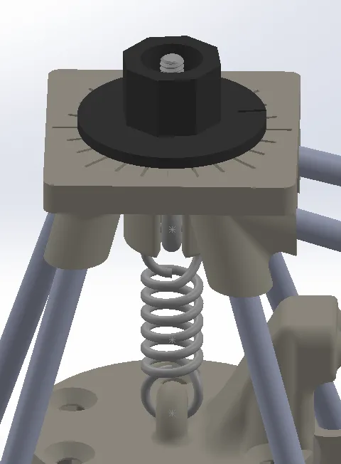
The knob and its notch ring.
The loading piece
The loading piece couples both springs to the load cell. If it broke, the shock could damage the sensor, so it is deliberately overbuilt: Formlabs Tough 2000 resin, filleted hoops to avoid stress concentrations, and a predicted stretch at 30 lbf too small to matter.
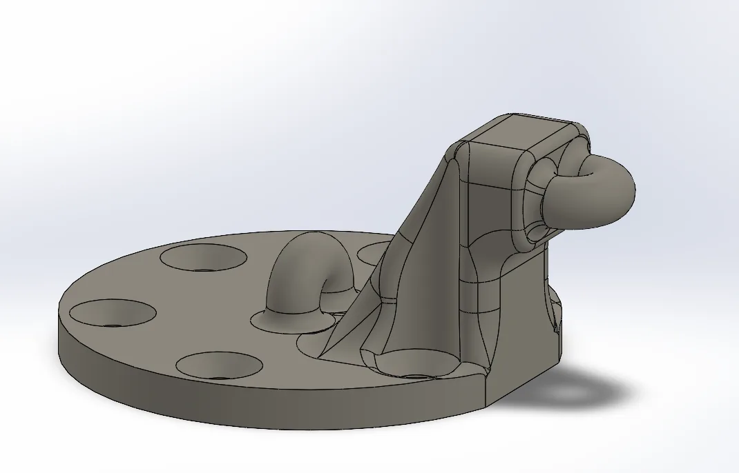
The loading piece: one hoop for each spring.
Build and proof test
Load-bearing joints are resin printed; the base plate is FDM. I bonded the steel tubes into the printed joints with J-B Weld while holding the structure at its maximum compressive load, so the cured joints carry no slack. Tight fits were toleranced at 0.01 in and loose ones at 0.02 in.
To check the loading piece I hung a 30 lbf weight from it for more than a minute; no deformation was visible.
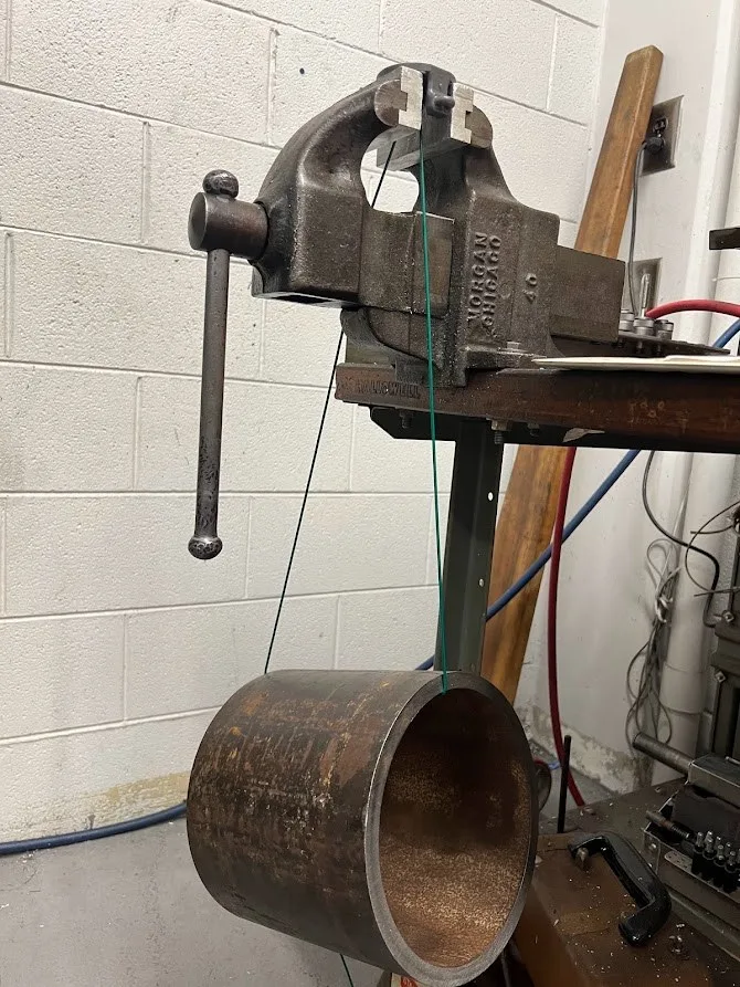
Proof test: 30 lbf on the loading piece.
No load-cell data was ever recorded. The data-acquisition hardware wasn’t available before the term ended, so the rig’s accuracy and the 0.148 lbf step are unverified.
The test plan it was built for
The user guide hands the rig to the next student with these steps, logged through a LabJack:
- Zero point. From the loosest setting, tighten until the reading just moves; that notch is zero, and each notch after it adds about 0.15 lbf.
- Creep. Hold a constant load and record over a set period.
- Hysteresis. Load and unload in steps with the knob.
- Thermal drift. Record while tunnel flow speed changes the temperature.
- Orientation. Repeat the above with the rig turned on the orientation stand.
What I took from it
This project pushed my CAD further than anything before it: parametric modeling, surface features and configurations, and a better order of operations so early guesses could change without breaking the model. It also taught me resin printing properly: orientation and curing decide whether a part reaches its rated strength. I presented the rig at the aerospace department’s Brown Bag seminar on November 11, 2022.
Documents
- Rig user guideWritten for the next user: design overview, installation and the planned test steps. December 2022.
- Research abstractNovember 2022.